- 您现在的位置:买卖IC网 > Sheet目录364 > ST40 (Littelfuse Inc)DIAC 35-45V BILATERAL TRIG DO214
Teccor ? brand Thyristors
Standard Bidirectional DIAC Trigger
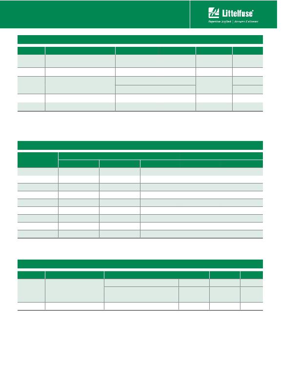
Electrical Characteristics (T J = 25°C, unless otherwise speci?ed)
Symbol
V BO
Description
Breakover/Trigger Voltage
Test Conditions
50/60Hz Sine Wave
Min
See Product
Selector Table
Max
See Product
Selector Table
Unit
V
V BO to V
ΔV BO
V BB
V BB (DYN)
I BO
Breakover Voltage Symmetry
Δ Breakback Voltage (Note 4)
Dynamic Δ Breakback Voltage (Notes 2 & 3)
Breakover Current
+V BO to -V BO
V BO to V 10mA
(*)
6mA
120 PPS
50/60Hz Sine Wave
5
15
10
2 (Note 1)
15
V
V
V
V
μA
(*) Only Applies to HT-60
Electrical Characteristic Notes:
1. Breakover voltage symmetry as close as 1V is available from the factory for
these products.
2. See Figure 4 and Figure 5 for test circuit and waveforms.
Product Selector
3. Typical switching time is 900 nano-seconds measured at I PK (Figure 4) across a
20 Ω resistor (Figure 5). Switching time is de?ned as rise time of I PK between the
10% to 90% points
4. See V-I Characteristics
Static Characteristics - Not Applicable
Part Number
XX-32
XX-32A/ 5761
XX-32B/ 5761A
XX-34B
XX-35
XX-36A/ 5762
XX-36B
XX-40
XX-60
MINIMELF
—
—
HTM-32B
—
—
—
—
—
—
Package Availability
DO-35
HT-32
HT-32A
HT-32B
HT-34B
HT-35
HT-36A
HT-36B
HT-40
HT-60
DO-214
ST-32
—
ST-32B
ST-34B
ST-35
ST-36A
ST-36B
ST-40
—
MIN
27V
28V
30V
32V
30V
32V
34V
35V
56V
V BO
MAX
37V
36V
34V
36V
40V
40V
38V
45V
70V
“XX” = HTM for MINIMELF
HT for DO-35
ST for DO-214
Thermal Resistances
Symbol
Description
Test Conditions
Maximum Lead Temperature: 85°C
DO-35
Value
100
Unit
°C/W
R
(J-L)
Junction to Lead
Maximum Lead Temperature: 90°C
DO-214
65*
°C/W
Maximum Lead Temperature: 87°C
MINIMELF
75
°C/W
R
(J-A)
Junction to Ambient
Free-Air
DO-35
278
°C/W
* Mounted on 1 cm 2 copper foil surface; two-ounce copper foil
HTxxx & HTMxxx & STxxx Series
338
Revised: July 9, 2008
?2008 Littelfuse, Inc.
Speci?cations are subject to change without notice.
Please refer to http://www.littelfuse.com for current information.
发布紧急采购,3分钟左右您将得到回复。
相关PDF资料
STRIKER
SURGE SUPPRESSR 120V 7OUT 6'CORD
SUPER-7
SURGE SUPPRESSOR 7 OUT 7' CORD
SUPER6TEL12
SURGE SUPPR 7OUT 12'CORD W/RJ11
SUPER6TEL
SURGE SUPPRESSOR 7OUT W/TEL
SUPER7COAX
SURGE SUPPRESSOR 7 OUT W/COAX
SUPER7TEL15
SURGE SUPPR 7OUT 15'CORD W/RJ11
SUPER7TEL
SURGE SUPPR 7OUT 7'CORD W/RJ11
SUPERPROZ
PROGRAMMER UNIVERSAL 40-PIN
相关代理商/技术参数
ST-40
制造商:Taiyo Electric Ind. 功能描述:
ST400/69/23
制造商:Block 功能描述:Control panel transformer, 400VA, 230V
ST40002B
功能描述:CURRENT LIMITER INRSH 40OHM 2A RoHS:是 类别:过电压,电流,温度装置 >> 涌入电流限制器 (ICL) 系列:ST 产品培训模块:Inrush Current Limiters Overview 标准包装:25 系列:- R @ 25°C:0.5 欧姆 R @电流:0.011 欧姆 电流 - 稳态最大值:36A 容差:±25% 直径:1.18"(30mm) 引线间隔:0.307"(7.80mm) 包装:散装 其它名称:570-1012MS320R536
ST-4000D
制造商:Holland Electronics 功能描述:Hand Held Signal Level Meter 制造商:HOLLAND ELECTRONICS 功能描述:HAND HELD SIGNAL LEVEL METER 46-870MHZ IN 10KHZ STEPS
ST4000DM000
制造商:Seagate Technology 功能描述:DESKTOPP HDD SATA 3.5IN 5900RPM - Bulk
ST4000DX000
制造商:Seagate Technology 功能描述:BARRACUDA 4TB 7200 RPM 128MB CACHE SATA 6.0GB/S 3.5 INTERNAL - Trays
ST4000NM0023
制造商:Seagate Technology 功能描述:SAS40007200RPM128CASHE3.5 FORM FACTOR - Trays
ST4000NM0033
制造商:Seagate Technology 功能描述:SATA40007200RPM128CASHE3.5 FORM FACTOR - Trays
